LEGO C# SDK – Enhancements & Challenges

Recap

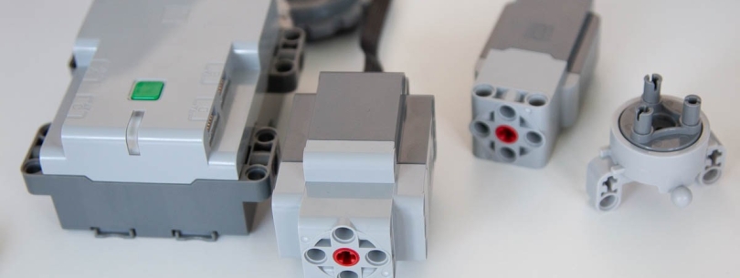
This is a follow-up to my previous post discussing how I went about creating a C# SDK for the most recent version of the LEGO specification for the Bluetooth (Low Energy) protocol used in a range of their PoweredUp products. Read more here.

Inputs (Sensors)

The biggest improvement so far has been the work to read sensory data from connected devices. There is a lot of upstream and downstream messages required to coordinate this which I detail below for those that are interested.

Input Modes

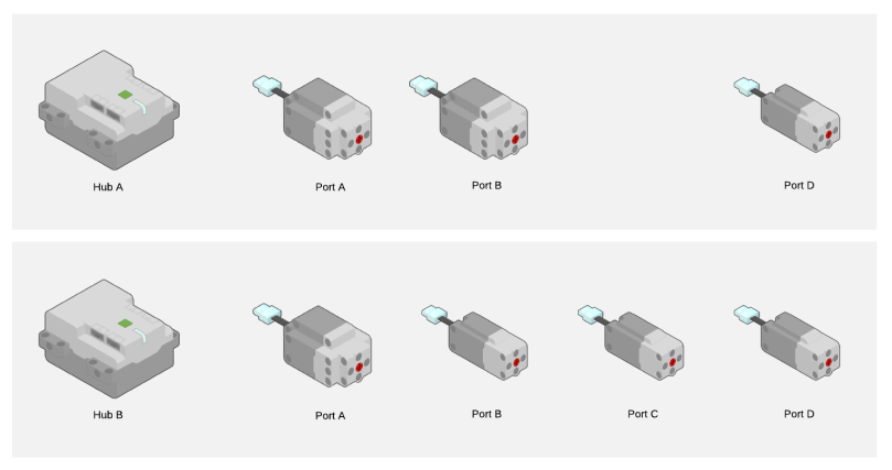
The input modes are a logical separation allowing a single connected device (e.g. motor) to have different modes of operation for which you can send (output) or receive (input) data.

The protocol allows us to interact with the connected device using either a single mode (e.g. Speed) or a combined mode where supported (e.g. Speed, Absolute Position, and Position).

Single Input

To use single input mode we need to set the desired input mode, delta to trigger updates, and flag whether to notify us (push data) or not (poll data).

This is done by sending a Port Input Format Setup (Single) message which contains:

  • Port # of the connected device (e.g. 0)
  • Mode we wish to set (e.g. Mode 1 / Speed)
  • Delta of change which should trigger an update (e.g. 1)
  • Notify flag whether to automatically send an upstream message when the delta is met.

You can be quite creative using single input. We can calibrate the min and max position of a linear actuator by switching the input modes as below:

  1. Switch input mode to Speed.
  2. Move to absolute minimum position using a lower than normal power (torque).
  3. Monitor changes to Speed until value drops to 0.
  4. Switch input mode to Position.
  5. Record current position as calibrated minimum for device.
  6. Switch input mode to Speed.
  7. Move to absolute maximum position using a lower than normal power (torque).
  8. Monitor changes to Speed until value drops to 0.
  9. Switch input mode to Position.
  10. Record current position as calibrated maximum for device.

These recorded min and max positions can be stored in the SDK against the device to act as constraints for further commands before they are forwarded onto the hub.

Combined Input(s)

Whilst single input is really simple to setup and can be used to make the connected device behave much more intelligently, it is inconvenient and inefficient to have to keep switching modes.

Combining modes allows us to inform the device what combination of modes we are interested in (based on a supported range of options) and receive a message that contains information (data sets) about all modes consolidated.

The setup of this is much more complicated based on how much information is device specific.

Prerequisites

Information about the connected device can be obtained by sending a Port Information Request message. We actually send this message twice so that we can obtain different information types:

  • Port Information
  • Possible Mode Combinations

Port Information provides information from the connected device about general capabilities (e.g. input, output, combinable, synchronizable) and the modes of operation for input and output.

Based on the the port having the capability of being combinable the subsequent message provides information about the range of mode combinations supported (e.g. Mode 1 + Mode 2 + Mode 3). We will need to reference which of these mode combinations we want to utilize later on.

Once we have this information we can determine how to interact with each mode. The main thing we are interested in for the purpose of combining inputs is the value format which communicates how many data sets to expect, the structure of the data etc.

To obtain this information we send a Port Mode Information Request message for each mode. This message contains:

  • Port
  • Mode
  • Information Type (e.g. Value Format)

The message will trigger a response which we can intercept. In the case of Value Format we get the following information:

  • Number of data sets
  • Data type (e.g. 8 bit)
  • Total figures
  • Decimals (if any)

With this information we should have everything we need to setup our combined input(s).

Setup

For combined input(s) the setup requires several messages.

Firstly we must lock the device to avoid subsequent steps from being treat as a single input setup. This is done using a Port Input Format Setup (Combined) message with the Lock LPF2 Device for setup sub-command.

Then, for each mode we wish to combine we need to send the Port Input Format Setup (Single) as detailed above.

Before we unlock the device we need to configure how the data sets will be delivered using another Port Input Format Setup (Combined) message, this time with the SetModeDataSet combination(s) sub-command.

This includes the combination mode we wish to use along with an ordered mapping of modes and data sets that we wish to consume.

An example payload could be:

  • 9 = Message Length
  • 0 = Hub Id
  • 66 = Message Type : Port Input Format Setup (Combined)
  • 0 = Port #
  • 1 = Sub-Command : SetModeDataSet combination(s)
  • 0 = Combination Mode Index
  • 17 = Mode/DataSet[0] (1/1)
  • 33 = Mode/DataSet[1] (2/1)
  • 29 = Mode/DataSet[2] (3/1)

Note: This should trigger a response message to acknowledge the command but I do not receive anything currently. Issue logged here in GitHub.

Finally, the device is unlocked using a third Port Input Format Setup (Combined) message with either UnlockAndStartWithMultiUpdateEnabled or UnlockAndStartWithMultiUpdateDisabled sub-commands.

Routines

Routines are simply a way to encapsulate reusable scripts into classes that can be run against devices and optionally awaited.

A good example of a routine is range calibration. By encapsulating the routine we can just apply it to as many devices as required any use constructor parameters for configuring the routine.

A routine has start and stop conditions which allow us to create iterative routines that are designed to repeat steps a number of times before completing.

It’s also possible to make the start and/or stop conditions dependent on the state of the device. For example, you could have a routine that stopped once the Speed dropped to zero etc.

Next Steps

I am keen to complete the combined input(s) setup once I have resolved the issue in GitHub. That will allow me to simplify the range calibration routine and start to create additional routines that are more dynamic and intelligent.

I also want to introduce a mechanism to relate control interfaces with commands and routines but before that I will probably need to implement a message buffer in the SDK to ensure that we can throttle downstream messages based on the limitations of the hubs capacity to process them.

C# SDK for LEGO Bluetooth (LE) Hubs

Tl;dr See the source code (and contribute) on Github.

LEGO & Bluetooth (LE)

LEGO have a new standard for communicating over Bluetooth (Low Energy) with compatible smart hubs that is documented here. The documentation is not being kept up to date but there is enough information there to fill in the gaps using a bit of trial and error.

Some of the older powered components use a different protocol and/or wiring specification. It is not the purpose of this post to document compatibility. I will detail any components I used during my development however.

Project Goal

The specification provides a good amount of detail but there are presently no C# SDKs to allow me to connect to a LEGO hub and control its connected devices remotely using a high level API.

As an example, I would like to be able to do the following…


using (var connectionManager = new BluetoothLEConnectionManager())
{
var connectionA = await connectionManager.FindConnectionById("BluetoothLE#BluetoothLEb8:31:b5:93:3c:8c-90:84:2b:4d:d2:62");
var connectionB = await connectionManager.FindConnectionById("BluetoothLE#BluetoothLEb8:31:b5:93:3c:8c-90:84:2b:4e:1b:dd");
var hubA = new TechnicSmartHub(connectionA);
var hubB = new TechnicSmartHub(connectionB);
// wait until connected
await hubA.Connect();
await hubB.Connect();
// wait until all 3 motors are connected to Hub A
var leftTrack = await hubA.PortA<TechnicMotorXL>();
var rightTrack = await hubA.PortB<TechnicMotorXL>();
var turntable = await hubA.PortD<TechnicMotorL>();
// wait until all 4 motors are connected to Hub B
var primaryBoom = await hubB.PortA<TechnicMotorXL>();
var secondaryBoom = await hubB.PortB<TechnicMotorL>();
var tertiaryBoom = await hubB.PortC<TechnicMotorL>();
var bucket = await hubB.PortD<TechnicMotorL>();
// sequentially calibrate each linear actuator using a torque based range calibration routine
await primaryBoom.RunRoutine(new RangeCalibrationRoutine(50));
await secondaryBoom.RunRoutine(new RangeCalibrationRoutine(50));
await tertiaryBoom.RunRoutine(new RangeCalibrationRoutine(40));
await bucket.RunRoutine(new RangeCalibrationRoutine(35));
// move forwards for 5 seconds
leftTrack.SetSpeedForDuration(50, 100, RotateDirection.Clockwise, 5000);
rightTrack.SetSpeedForDuration(50, 100, RotateDirection.CounterClockwise, 5000);
await Task.Delay(5000);
// rotate boom for 3 seconds
turntable.SetSpeedForDuration(100, 100, RotateDirection.CounterClockwise, 3000);
await Task.Delay(3000);
// reposition boom
primaryBoom.SetSpeedForDuration(100, 100, RotateDirection.Clockwise, 3000);
secondaryBoom.SetSpeedForDuration(75, 100, RotateDirection.CounterClockwise, 3000);
tertiaryBoom.SetSpeedForDuration(100, 100, RotateDirection.CounterClockwise, 2000);
await Task.Delay(3000);
// lift bucket
bucket.SetSpeedForDuration(50, 100, RotateDirection.Clockwise, 2000);
}

view raw

Example.cs

hosted with ❤ by GitHub

I want to abstract the SDK from the connection so that I can distribute the Core as a .NET Standard package that can be used by different application types (e.g. UWP or Xamarin).

It should be possible to interact at a low level issuing commands in a procedural manner but provide an opportunity to eventually register additional information about the model being controlled so that more intelligent instructions can be executed using calibrated constraints and synchronized ports etc.

For this project I used the LEGO Technic set: Liebherr R 9800 (41200). It comes bundled with:

  • 2 x LEGO Technic Smart Hub (6142536)
  • 4 x LEGO Technic Motor L (6214085)
  • 3 x LEGO Technic Motor XL (6214088)

A Control+ application provides connectivity with the model but isn’t extensible or compatibility with custom builds. Other applications provide basic programming capabilities using arrangements of blocks but this will be the only C# SDK to provide more control to users without being dependent on iOS or Android app support.

Functional Overview

Based on the model referenced above, the Control+ components are connected as below:

41200 Configuration

Each Hub/Port controls different aspects of the model as follows:

  • Hub A
    • Port A : Left track
    • Port B : Right track
    • Port D : Turntable
  • Hub B
    • Port A : Primary Boom
    • Port B : Secondary Boom
    • Port C : Tertiary Boom
    • Port D : Bucket

SDK Types

In order to facilitate interop between the SDK and the remote hubs we will have the following types:

IConnection

This interface abstracts the BluetoothLE device connection from the SDK so that it can be used to subscribe to notifications and to read or write values without us being tightly coupled to a specific implementation (e.g. UWP).

Each IConnection has a one to one relationship with a BluetoothLE device based on the device ID.

IMessage

An IMessage is a byte[] that encapsulates all IO communication between the physical hub and the derived Hub class(es). Different concrete implementations provide strongly typed properties (usually enums) to make the interop more readable and to simplify parsing the byte streams.

Hub

This is an abstract class that all specific Hubs must implement and it encapsulates the interactions between the Hub and its assigned IConnection.

A Hub is responsible for taking actions based on messages it received from the IConnection and for writing values based on any outbound IMessage the Hub produces.

Device

This represents anything which can be connected to the Hub either by a physical port (e.g. Motor) or a virtual port (e.g. Internal sensor).

Each concrete implementation of a Device must correspond with an IODeviceType enum value since the Hub will be responsible for instantiating a Device and assigning it to a port.

Devices can produce messages and extensions expose convenience methods based on composition interfaces (e.g. IMotor).

Video Example

More Information

For the source code, please see the Github repo: https://github.com/Vouzamo/Lego

If anyone would like to become a contributor that would be much appreciated as this will be the communication standard for all LEGO hubs moving forward and I would like to get this working for all the potential hubs and devices available.

Other enhancement could include:

  • Registration of control components to for real-time user input.
  • Registration of virtual components for real-time API input (e.g. RESTful).
  • Registration of device constraints to manage calibration for absolute extremes to constrain what commands can be sent to the hub for a given port/device.
  • Registration of device commands that should be invoked based on Hub state or incoming IMessage conditions.


Do NOT Purchase the HTC Vive

Background

I purchased my HTC Vive less than 2 years ago from Amazon. I was initially impressed with it despite its limitations. The low resolution meant that it was far from perfect but compared to other devices on the market it had more capabilities such as room scale tracking and I felt that I had some hardware that I could enjoy for several years and looked forward to the software that would inevitably come.

It didn’t happen. Pretty much all the software is a glorified tech demo whilst competitors such as Facebook with the Oculus Rift and Sony with PSVR have been more considerate of their customers by forming partnerships and exclusive deals to produce software that is consumer focused and can engage you for more than a few minutes.

HTC instead, have decided to focus all their energy on corporate VR such as potential VR arcades, conferences etc and completely ignored the consumers who invested heavily in the Vive. This couldn’t be more evident than the reaction to their latest product – HTC Vice Pro. It is $800 just for the headset, will not be compatible with an upcoming wireless adapter without purchasing additional compatibility kits, and has been reported to be much heavier and less comfortable than the original Vive. Hence why no-one is buying it.

Faulty

To my frustration, one of the base stations recently developed a fault. This particular fault is called fault 03 and is extremely common. So common in fact that when I raised an RMA ticket with HTC about this they confirmed that…

“The repair process would take up to 2 weeks as we have been seeing a lot of delays on the repair processes, we are striving to see it happening much faster but I cannot promise a faster process”.

You can read more about fault 03 here:

After providing my serial numbers for both the headset and the base station (and chasing up after several days of being ignored) I was informed that a repair would only be possible if I paid $90. I will NOT be paying $90.

This means that HTC think it is acceptable for a key component in room scale tracking to fail within less than 2 years. This is a component that remains stationary and mounted to the corner of a play space. I can’t even comprehend how HTC would think anyone would agree to spending $90 for something that would cost $135 to replace with a completely new unit.

What makes all of this much worse is that HTC Vive’s are currently shipping with tweaked base stations that demonstrates the original design had issues that needed to be fixed but HTC are not doing the right thing for the customers that have the failed design prone to faults and instead expect them to pay the wholesale price of a replacement for it to be ‘repaired’. See: https://www.roadtovr.com/latest-vive-shipping-with-tweaked-base-stations-redesigned-packaging/

In summary, HTC Vive hardware is not expected to last more than a year, hence the warranty and lack of any support from HTC once that year has expired.

What Next

I will not be replacing or repairing my base station. HTC have made their position clear. They are not creating products for consumers and do not care about their customers. Instead I will be selling the remainder of my HTC Vive hardware.

The HTC Vive is already not able to compete on price with its competitors and doesn’t have any differentiating features anymore. The software available remains inferior to other VR systems and, as such, I will re-invest my money in one or more competing products such as the Oculus Rift from Facebook.

Please take this as a warning that HTC will not provide any after-sales support and do not value your custom.

AngularJS for a multi-page website? You’re Doing It Wrong!

There are some exceptions to the sweeping statement I am about to make but I am growing tired of seeing the same mistake being made when choosing a technology stack for a multi-page web application implementation…

Jeff Goldblum quote from Jurassic Park

So… What’s Wrong With AngularJS?

AngularJS is a fantastic JavaScript framework and an excellent technology choice when building a web application with a single page architecture. There is nothing inherently wrong with it that should exclude it from consideration if you are building a dashboard style application that you want to be interactive and are looking to mimic a native application user experience.

Can I use it for a website implementation?

You can, but before you do you should ask yourself some questions:

  1. Does your implementation have more than one page?
  2. Does progressive enhancement give you everything that a SPA would offer?
  3. Do I care about SEO?

If you answer ‘yes’ to any of the above questions, you should seriously consider an alternative approach.

My web application DOES have more than 1 page

If you are building a web application to serve requests for different pages of content then a single page architecture is counter intuitive and akin to forcing a square peg into a round hole.

You are going to invest time and resources into producing a web application that might look fantastic but falls over completely without JavaScript enabled.

Neither hash bangs (#!) or HTML’s history API have provided a solution to the problems when trying to implement a multi-page web application using a single page architecture JavaScript framework.

How can progressive enhancement help?

Despite all the advances in crawler technology, a server-side technology is still far superior at serving multi-page content. Server-side technologies are far more mature than the emerging JavaScript frameworks and the total cost of ownership for equivalent solutions are much lower.

The primary reason I hear for wanting to use AngularJS or any of the other SPA JavaScript frameworks is to have a native app feel by removing the visible loading of a page when browsing pages on the web application.

This can very easily be achieved without the bloat that comes with a framework such as AngularJS. You can use JavaScript to override the default behavior of a hyperlink so that you request the page via ajax, parse the content from an inner DOM container, and drop it onto the current page.

Alternatively, you can expose CaaS so that the initial page load is rendered server-side with subsequent updates being fetched via Ajax. This is different to an SPA implementation in that the content is still rendered on the server-side before being injected into the page by JavaScript.

What about SEO?

If you serve a single page architecture that takes over the routing of your website you give your visitors a different browsing experience than the search engine crawlers that will visit you.

The usual proposed solution to this is to detect crawlers and serve a different page that can be effectively crawled so now you have two implementations to maintain instead of just the one.

You can use the HTML5 history API and push state to modify the url as you navigate SPA implementation but unless this url is stateless and would present the same page and state as you currently have it isn’t a consistent experience. The same consideration applies when considering social sharing. A url should be stateless so that when you share a url it reflects the content you initially shared rather than contextual content based on the journey you took to arrive at that url.

The far better approach is to have a multi-page web application that can serve the appropriate content by url using hyperlinks and other HTML standard features. Then, using custom JavaScript or a lightweight JavaScript framework, introduce progressive enhancement for those visitors that have it enabled.

This will give you a consistent experience for crawlers and visitors whilst only maintaining a single implementation. You’ll also be able to achieve exactly the same user experience that a SPA JavaScript framework can provide but at a far lower total cost of ownership.

So SPA is great, but not for multi-page websites

Another benefit is that, with the business logic and rendering primarily on the server-side you do not need to come up with the solution to problems that have already been solved beforehand in areas such as security, state, social etc.

It’s a shame to use the wrong technology stack just because you failed to ask the right questions before investing time and resources into a new web application implementation. Especially if the only reason for using the wrong technology was because it is new and trendy or because the CEO heard good things about it.

The 1 Killer Feature Missing from SDL Web 8 (formerly Tridion)

For several years I have worked on a number of different SDL Web 8 and Tridion implementations and on almost every single one I have wanted an elusive feature that is not available out of the box.

When you are preparing a website for content management, you invariably have to make a compromise between having style fields in the content schema metadata or in the component template metadata. There is a trade-off in either case because, if you put style fields in the content schema you’ll have to duplicate content for the purpose of styling – that’s BAD! However, the alternative results in potentially having LOTS of component templates for all the style variations. If you have fields for the block size, color, borders etc you can soon run into problems.

The solution to this would be to have the schema only model content and it’s metadata as intended. To have the component template metadata include instructions that dictate how it should be rendered. And to have style or theme fields on component presentation metadata – a structure that doesn’t exist until you combine a component with a suitable component template.

There is even a sensible place to curate these fields in the UI…

Capture
Edit Page UI in SDL Tridion 2013

The component presentation metadata would feature as a contextual tab alongside the Component Presentation and Target Groups tabs and would be specific to the highlighted component presentation and stored with the component presentation in the CM data store.

Similar to how a component template can define it’s parameters schema or metadata schema, it should be able to define it’s component presentation metadata schema also so that the correct fields are presented accordingly. You might want different component presentation metadata for different component templates right?

This would require some architectural additions to the product but imagine being able to use an IComponentPresentation in DD4T or DXA to access the component presentation metadata with information about how to theme this particular template? The component template remains responsible for how it should be rendered but there is more information obtained when the content editor selected this component template to inform us how they want to use it for this particular occurrence.

This doesn’t break the way any of the concepts are currently applied or implemented but extends them with a new feature that would vastly improve the re-usability of components and/or component templates without limiting the flexibility in the rendering phase of content delivery.

We are often able to customize and extend the product with a wealth of excellent extension points from GUI extensions and CoreService APIs etc. However, because this would require some extension of the CM data store, it would be better suited as an extension to the core product opposed to a community developed extension.

Anatomy of a URL

Overview

I often find that there are some misconceptions regarding the structure of a URL and want to produce a clear definition of a properly formatted URL along with an explanation of the constituent parts and the purpose they serve.

URL is an acronym of Uniform Resource Locator and contains all the information required to identify the server responsible for responding to the request along with the information that it needs to locate the specific resource.

Dissecting the URL

Here’s a diagram to dissect the URL:

vouzamo-wordpress-com-anatomy-of-a-url

Scheme

The scheme (also referred to as protocol) describes the protocol that should be used. Common protocols include http (Hypertext Transfer Protocol), https (Secure Hypertext Transfer Protocol), ftp (File Transfer Protocol).

Every URL requires a scheme but modern browsers have made us lazy by automatically adding a scheme and absolute root (usually http://) when an authority is entered into the address bar.

Absolute Root

This is required for any absolute URL and, if omitted, would result in a relative URL. Modern browsers will add the absolute root to requests typed into the address bar appended to the default scheme. The double forward slash ‘//’ precedes an authority.

A common usage of the absolute root is to request a resource with the same scheme as the current resource without having to include it explicitly (e.g. ‘//www.example.com/some-image.png’). This is particularly useful on HTML pages which can be served using either the http or https protocols and need to request their associated resources accordingly.

Authority

This should be familiar as every URL we type into an address bar will contain one (unless we use the corresponding IP address instead). The authority is the address of a server on the network that can be looked up using DNS (Domain Name System).

Here’s a diagram to dissect the authority:

vouzamo-wordpress-com-anatomy-of-a-hostname

Subdomain

This is optional but there are some common subdomains including www, mail, ftp etc. A request to http://www.example.com is a different to a request to example.com but because the www subdomain is so commonly associated with the Domain the domain administrator will often configure a redirect from example.com to http://www.example.com.

Domain

This must be unique for each top level domain (e.g. .com) and often describes the registered authority.

Top Level Domain

A top level domain is one of the domains at the highest level in the hierarchical Domain Name System.

Port

The port is required for all requests but modern browsers will include a default automatically for certain schemes. It will include port 80 for the http scheme, port 443 for the https scheme, and port 21 for the ftp scheme. A colon will prefix the port number in a URL.

Path

The path informs the server of the specific location where it can retrieve the resource. It must start with a forward slash ‘/’ and historically denoted a file system location relative to a web application root.

The simplest path is ‘/’ and it is possible for multiple paths to reference the same resource e.g. ‘/about-us’, ‘/about-us/’, and ‘/about-us/index.html’ could all refer to the same resource but this shouldn’t be taken for granted. It depends how the server has been configured and these are different addresses and it is common for administrators to configure redirects from ‘/{path}’ and ‘/{path}/’ to ‘/{path}/{default document}’.

Query

The query exposes some parameters for the server to consume and must be prefixed with a question mark ‘?’. The format of a parameter is ‘{parameter}={value}’. Multiple parameters can be specified by using ampersand ‘&’ as a delimiter and the same parameter can be included multiple times with different values.

Fragment

The fragment is never sent to the server and is the final part of a URL. Its purpose is to identify a specific location within a resource. There can only be a single fragment optionally appended to the URL and it must be prefixed with a hash ‘#’.

What are Methods?

Methods are specific to the Hypertext Transfer Protocol (including https) and provide a way of differentiating between different intentions for the same URL. We use verbs to describe these intentions and the variations are below:

vouzamo-wordpress-com-anatomy-of-the-methods

HEAD

This is identical to the GET method with the exception that the server must NOT return a response body.

GET

This is the most commonly used method and the method that is used when entering an address into a browser. It will use the URL to locate and return a resource.

POST

This method is used to send information to the server. The function performed by the POST method is determined by the server and may not result in a resource that can be identified by the URL. In this case a status code in the response can describe success or failure.

PUT

This is similar to the POST method but, if the URL refers to an already existing resource, the server should consider this a modified version.

DELETE

This method informs the server to delete any resource at the specified URL. If the deletion is deferred instead of being deleted immediately then an accepted status code can be used in the response.

CONNECT

This method can be used with a proxy to switch to being a tunnel (e.g. SSH Tunneling).

OTHERS

There are other methods such as TRACE and methods are subject to being extended by the W3C HTTP specification in the future. See https://www.w3.org/Protocols/ for more information.

ThreeJS : Heads Up Display

This is part of a series of posts on Project Grid.

  1. Project Grid
  2. ThreeJS : Getting Started
  3. ThreeJS : Creating a 3D World
  4. ThreeJS : Heads Up Display
  5. ASP.NET Core & Azure DocumentDB: Modeling the Domain

I would urge you to read the previous blogs in this series if you haven’t already done so. But, if you are impatient (like me) then you can download the source code so far from Google Drive.

What is a HUD?

A HUD (or heads up display) is a 2D user interface that overlays our 3D scene and provides useful information to help us interact with the geometry.

We facilitate a HUD by having a second scene (sceneHud) in which we can manage our HUD objects and an orthographic camera (cameraOrthographic) to render them in 2 dimensions.

 function renderScenes() {
     renderer.clear();
     renderer.render(sceneMain, cameraPerspective);
     renderer.clearDepth();
     renderer.render(sceneHud, cameraOrthographic);
 }

In the above code you can see we have been rendering our sceneHud all along but since it doesn’t contain anything yet, there is nothing visual as a result.

Populating Our HUD

Our HUD is going to be responsible for rendering a 2D projection of pointers to some tracked 3D objects from sceneMain.

We want to project an imaginary circle onto our HUD and render a cone over each tracked object. If the tracked object falls inside the imaginary circle, we can orientate it towards the camera to render a circular silhouette. Otherwise, we can orientate it to point towards its target object and position it on the circumference of our imaginary circle. Additionally, we are going to ignore any tracked objects that are behind the near clipping plane of our perspective camera.

grid-hud

This should give us something like the image above where we have a combination of spheres and cones to track objects and help us navigate towards them.

Note: In the future we will likely replaces the spheres that overlay tracked objects within the 2D projected circle with some identifying information instead.

Adding Objects to the HUD

The first stage is to create a new THREE.Group to manage the HUD objects and a THREE.Mesh for each cone.

Add the following functions:

function initHudData() {
    hudGroup = new THREE.Group();

    sceneHud.add(hudGroup);
}

function addHudData(trackedItem) {
    var hudGeometry = new THREE.ConeGeometry(0.1, 0.2, 16);
    hudGeometry.rotateX(Math.PI * 0.5);
    var hudMaterial = new THREE.MeshPhongMaterial({ color: 0xffffff, side: THREE.DoubleSide });

    var hudData = new THREE.Mesh(hudGeometry, hudMaterial);

    hudData.scale.set(200, 200, 200);
    hudData.visible = false;
    hudData.tracked = trackedItem;
    
    hudGroup.add(hudData);
}

You’ll need to ensure you call the initHudData function from within your initSceneHud function but now, when creating your items in the initData function you can track them by calling the addHudData function and passing the data.

function initData() {
    ...
    for (var i = 0; i < 15; i++) {
        ...
        addHudData(data);

        itemGroup.add(data);
    }
    sceneMain.add(itemGroup);
}

Note: You won’t be able to see anything yet because we set the visible property of the HUD objects to false when we initialized them.

Animating the HUD Objects

We will need to update the visibility and orientation of each of our HUD objects based on the orientation of the camera and the position of items in the sceneMain relative to the camera.

We need to iterate over each HUD object and check if it is in front of the near clipping plane of the cameraPerspective. This will determine the visibility of each respective HUD object.

Add the following functions:

function checkCameraPlane(obj, camera) {
    var cameraDirection = camera.getWorldDirection();
    var objectDirection = new THREE.Vector3(0, 0, 0);
    objectDirection.subVectors(obj.position, camera.position);

    return cameraDirection.dot(objectDirection) >= 0;
}

function findHudPosition(obj, camera) {
    var vector = new THREE.Vector3();

    obj.updateMatrixWorld();
    vector.setFromMatrixPosition(obj.matrixWorld);
    vector.project(camera);

    vector.x *= (screenWidth / 2);
    vector.y *= (screenHeight / 2);
    vector.z = 1;

    return vector;
}

The checkCameraPlane function will determine the dot product for a vector representing the orientation of the camera and a vector between the camera and an object. If the dot product is greater than or equal to zero, we can consider the object to be in front of the camera.

The findHudPosition function will project a 3D perspective world position to a 2D orthographic screen position.

Add the following function:

function updateHudData() {
    var centerPoint = new THREE.Vector3(0, 0, 1);

    hudGroup.children.forEach(function (data) {
        var target = data.tracked;

        if (checkCameraPlane(target, camera)) {
            var position = findHudPosition(target, camera);
            
            if (position.distanceTo(centerPoint) <= 400) {
                data.lookAt(cameraOrthographic);
            } else {
                data.lookAt(position);
                position.clampLength(0, 400);
            }

            data.position.set(position.x, position.y, position.z);
            data.visible = true;
        } else {
            data.visible = false;
        }
    });
}

We need to ensure our updateHudData function is called from our animate function after we call our updateData function.

If you run your code now, you should the HUD items should be rendered and will point towards their respective tracked objects (or the camera when within the imaginary circle).

Resources

You can see a working version here.

You can watch a video on YouTube.

You can see the source code on GitHub or download a working example from Google Drive.

What Next?

We are just generating random data for our scene and it is not persistent. In the next post we’ll be using ASP.NET Core and Azure DocumentDB to create a data driven REST API that will provide the data for our Grid.

ThreeJS : Creating a 3D World

This is part of a series of posts on Project Grid.

  1. Project Grid
  2. ThreeJS : Getting Started
  3. ThreeJS : Creating a 3D World
  4. ThreeJS : Heads Up Display

I would urge you to read the previous blogs in this series if you haven’t already done so. But, if you are impatient (like me) then you can download the source code so far from Google Drive.

Fundamentals of 3D

This post is going to assume a basic knowledge of 3D terminology. Some basic definitions are below but I would encourage some additional reading if you aren’t already familiar.

3D fundamentals

  • Vertex (pl: vertices) – An individual point.
  • Edge – A vectors connecting 2 vertices.
  • Face – A sequence of edges to describe a polygon.
  • Polygon – A sequence of 3 or more edges to describe a face that resides on a single plane.
  • Vector – a direction combined with a magnitude represented using Cartesian coordinates.

Perspective Point Cloud

A point cloud is a particle system where each particle is part of the same geometric structure. A collection of multiple points in 3D space that can be represented by vertices without any edges connecting them to each other. The points can move by changing the coordinates for their specific vertex or the cloud can be moved by changing the position of the collective geometry.

We are going to create a point cloud that will be used to help orientate our camera in 3D space. As we move around the point cloud will give us some perspective of how we are moving relative to the stationary points.

In ThreeJs a point cloud depends upon some geometry and a material. We will be using the PointsMaterial since we want to be able to render each point individually with a texture. We are going to distribute the vertices of our point cloud over a cube that contains our camera.

point cloud

Add the following function:

function initPointCloud() {
    var points = new THREE.Geometry();
    var material = new THREE.PointsMaterial({
        color: 0xffffff,
        size: 0.1,
        map: new THREE.TextureLoader().load('textures/particle.png'),
        transparent: true,
        alphaTest: 0.5
    });

    var size = 15;

    for (var x = -size; x <= size; x++) {
        for (var y = -size; y <= size; y++) {
            for (var z = -size; z <= size; z++) {
                var point = new THREE.Vector3(x, y, z);
                points.vertices.push(point);
            }
        }
    }

    particleSystem = new THREE.Points(points, material);
    sceneMain.add(particleSystem);
}

Note: Ensure you have a suitable texture to load using the TextureLoader and that the path is correct. You can download my example texture from Google Drive.

Ensure you are calling the initPointCloud function from your init function. You should be able to run your code and navigate the scene using WASD to move and mouse click and drag to look around.

This looks pretty cool and helps us orientate ourselves but we can very quickly move beyond the range of the point cloud. What we need to do it to allow it to move with the camera but in such a way that we still feel like we are moving relative to it.

Animating the Scene

Our camera is able to move in 3D space and can be at any theoretical coordinates. We can represent our coordinates in the format [x,y,z] where x is our position along the x-axis, y along the y-axis, and z along the z-axis. Our camera can move gradually from one position to another. As it moves it will be at various positions such as [0.31, 1.57, -7.32] etc.

Our point cloud is stationary at position [0,0,0] and has vertices at various integer positions such as [1,2,3]. If we want to ensure that the point cloud moves with our camera we can simply update the position of the geometry within our animate function.

To retain the perspective of moving within the point cloud we must only update the point cloud within integer increments as the camera moves beyond a threshold, otherwise it will appear to be stationary relative to the camera.

Add the following function:

function updatePointCloud() {
    var distance = cameraPerspective.position.distanceTo(particleSystem.position);

    if (distance > 2) {
        var x = Math.floor(cameraPerspective.position.x);
        var y = Math.floor(cameraPerspective.position.y);
        var z = Math.floor(cameraPerspective.position.z);

        particleSystem.position.set(x, y, z);
    }
}

This function will check for the magnitude distance between the main camera and the point cloud. When it exceeds a threshold of 2 (in any direction), the point cloud position will be updated with the nearest integer coordinates to the camera. This will be a seamless change the the user because all the visible points will be rendered in exactly the same positions.

Ensure you are calling the updatePointCloud function from your animate function (before renderScenes). Now, if you run your code again, you should get the same effect as before but you’ll not be able to move outside the range of the point cloud.

Add Some Points of Interest

Okay, we have a scene, a camera, and a point cloud that gives us perspective when moving. Now we need something to represent the data we want to show later on. I am going to use a colored sphere as I will revisit later to customize the geometry and material based on the data.

Until we have a service that can provide the data that should be added to the scene I will just generate some randomly.

Add the following functions:

function initData() {
    itemGroup = new THREE.Group();

    var geometry = new THREE.SphereGeometry(0.1, 32, 32);
    var material = new THREE.MeshBasicMaterial({ color: 0xff0000, wireframe: true, transparent: true, opacity: 0.5 });

    for (var i = 0; i < 15; i++) {
        var x = getRandom(-20, 20);
        var y = getRandom(-20, 20);
        var z = getRandom(-20, 20);

        var data = new THREE.Mesh(geometry, material);
        data.position.set(x, y, z);

        itemGroup.add(data);
    }

    sceneMain.add(itemGroup);
}

function getRandom(min, max) {
    var min = Math.ceil(min);
    var max = Math.floor(max);

    return Math.floor(Math.random() * (max - min)) + min;
}

This function creates a new group with 15 points of interest. Each point of interest is positioned randomly between -20 and 20 on each axis. Ensure you are calling the initData function from your init function.

A sphere looks okay but it’s much more interesting whilst rotating. Add the following function:

function updateData() {
    itemGroup.children.forEach(function(data) {
        data.rotation.x += 0.01;
        data.rotation.y += 0.01;
        data.rotation.z += 0.01;
    });
}

Ensure you are calling the updateData function from your animate function (before renderScenes). If you run the code you’ll be able to navigate your scene to find each of the 15 points of interest.

Next Steps

Whilst we can navigate our scene and find the points of interest, it is difficult to keep track of where they are relative to your current position – especially when they are far away as they are not visible over a certain distance.

In the next post we will add some HUD (heads up display) features to track the points of interest and provide a visual indicator of their position relative to ours. If you want to download an example of what we have created so far you can do so from Google Drive.

ThreeJS : Getting Started

This is part of a series of posts on Project Grid.

  1. Project Grid
  2. ThreeJS : Getting Started
  3. ThreeJS : Creating a 3D World
  4. ThreeJS : Heads Up Display

What are we going to build?

In my previous Project Grid post I discussed the concept of visualizing content within a 3d grid so I am going to build a 3d world space in which I can plot points, add some temporary controls to navigate world space, and some HUD (heads up display) functionality to help me find plotted points.

You can see a working example here.

I want to use WebGL to render the scene(s) and I will be using ThreeJS to build my scene(s). ThreeJS is a JavaScript library that provides a familiar and consistent way to build  scenes using JavaScript.

Setting the Scene

We can start by creating a new html page. We need to include a <script> for the ThreeJS library. For development / PoC purposes we can just link to the latest build (http://threejs.org/build/three.js) but for a production application you’d want to reference a specific versions and would likely self-host.

We’ll also want to create an in-line <script> element for our scene with some variables, an init function and an animate function.

You should now have something like this:

var container, screenWidth, screenHeight;
var sceneMain, sceneHud;
var cameraPerspective, cameraOrthographic;
var controls, renderer, clock;
var groupItems, particleItems, hudItems;

init();
animate();

function init() {

}

function animate() {

}

We are going to need a WebGL renderer. Add the following function:

function initRenderer() {
    renderer = new THREE.WebGLRenderer({
        antialias: true,
        alpha: true
    });

    renderer.setClearColor(0x000000, 0);
    renderer.autoClear = false; // We want to draw multiple scenes each tick
    renderer.setPixelRatio(window.devicePixelRatio);
    renderer.setSize(screenWidth, screenHeight);

    container.appendChild(renderer.domElement);
}

Next, we need to initialize our main scene and our HUD scene. Add the following functions:

function initSceneMain() {
    sceneMain = new THREE.Scene();
    sceneMain.fog = new THREE.Fog(0x000000, 1, 60);
}

function initSceneHud() {
    sceneHud = new THREE.Scene();
    sceneHud.add(new THREE.AmbientLight(0xffffff));
}

Now we have some scenes, we should create some cameras. Add the following function:

function initCameras() {
    cameraPerspective = new THREE.PerspectiveCamera(
        30,
        1600 / 900,
        0.1, 55
    );

    cameraOrthographic = new THREE.OrthographicCamera(
        1600 / -2,
        1600 / 2,
        900 / 2,
        900 / -2,
        1, 1000
    );
}

Note: Some of the parameters (1600 and 900) are arbitrary as we’ll be updating them after calculating the window dimensions anyway.

We are going to render the main scene with the perspective camera followed by the HUD scene with the orthographic camera. To do this, lets add a render function:

function renderScenes() {
    renderer.clear();
    renderer.render(sceneMain, cameraPerspective);
    renderer.clearDepth();
    renderer.render(sceneHud, cameraOrthographic);
}

Now we have a way to render our scenes we can wire it up from our existing animate function:

function animate() {
    requestAnimationFrame(animate); // This will handle the callback

    var delta = clock.getDelta();

    // Any changes to the scene will be initiated from here

    renderScenes();
}

All that remains is to wire up our existing init function:

function init() {
    container = document.createElement('div');
    document.body.appendChild(container);

    // We'll replace these values shortly
    screenWidth = 1600;
    screenHeight = 900;

    clock = new THREE.Clock();

    initRenderer();
    initCameras();
    initSceneMain();
    initSceneHud();
}

You should be able to test your scene now. It’s not very exciting but we haven’t added anything to it yet. Provided you aren’t getting any console errors, everything is working correctly (so far).

Creating a Background

For our 3d background we are going to use a skybox. A skybox is a very large cube with textures applied to the inside faces. Our camera and everything else it can see is inside this cube so those textures act as the background.

You will need 6 textures – 1 for each face of the cube. You can download my example textures from Google Drive. Add a folder for textures, and within, add another folder for skybox.

To create a skybox from the textures, add the following function:

function initSkybox(scene) {
    var skyboxPath = 'textures/skybox/';
    var skyboxFormat = 'png';

    var skyboxTextures = [
        skyboxPath + 'right.' + skyboxFormat,
        skyboxPath + 'left.' + skyboxFormat,
        skyboxPath + 'up.' + skyboxFormat,
        skyboxPath + 'down.' + skyboxFormat,
        skyboxPath + 'front.' + skyboxFormat,
        skyboxPath + 'back.' + skyboxFormat,
    ];

    var skybox = new THREE.CubeTextureLoader().load(skyboxTextures);
    skybox.format = THREE.RGBFormat;

    scene.background = skybox;
}

If you update your initSceneMain() function and add a function call for initSkybox(sceneMain) you should see a monochrome background in the browser. You should see something like this:

Grid Skybox

Note: You’ll need to serve the html page rather than just open it in the browser. If you try to use a file protocol ThreeJS will throw an CORS error when trying to load the texture(s).

Taking Control

We are going to use some ready made controls for ThreeJS to allow us to quickly navigate around in our scene. We can replace these later with our own custom controls. You’ll need to include another external script in your <head> for http://threejs.org/examples/js/controls/FlyControls.js.

Add a function for initializing the controls and binding them to our perspective camera:

function initControls(target) {
    controls = new THREE.FlyControls(target);
    controls.movementSpeed = 5;
    controls.rollSpeed = Math.PI / 12;
    controls.domElement = container;
    controls.dragToLook = true;
}

Add a function call for initControls(cameraPerspective) to your init function and update your existing animate function to update the controls:

function animate() {
    ...
    // Any changes to the scene will be initiated from here 
    controls.update(delta);
}

Now you can use mouse click / drag to look around within your scene. You can also use WASD to move but until you render something you’ll not be able to tell you’re moving yet.

Finishing Touches

We need to account for the window dimensions changing if a browser gets resized or if orientation changes on a mobile device. Add the following functions:

function initWindow() {
    screenWidth = window.innerWidth;
    screenHeight = window.innerHeight;

    renderer.setSize(screenWidth, screenHeight);
    resetCameras();
}

function resetCameras() {
    cameraPerspective.aspect = screenWidth / screenHeight;
    cameraPerspective.updateProjectionMatrix();

    cameraOrthographic.left = screenWidth / -2;
    cameraOrthographic.right = screenWidth / 2;
    cameraOrthographic.top = screenHeight / 2;
    cameraOrthographic.bottom = screenHeight / -2;
    cameraOrthographic.updateProjectionMatrix();
}

Ensure that you update the init function to call initRenderer, initCameras, initWindow, then everything else. The order is important. Lastly, you can add an event handler to call your initWindow function when the window is resized:

window.addEventListener('resize', initWindow, false);

Next Steps

In the next post we will start adding objects to our scene(s) and animating them. If you want to download an example of what we have created so far you can do so from Google Drive.

Project Grid

This is part of a series of posts on Project Grid.

  1. Project Grid
  2. ThreeJS : Getting Started with ThreeJS
  3. ThreeJS : Creating a 3D World
  4. ThreeJS : Heads Up Display

Conceptual Overview

This is a multi-part series of blog posts on a project to create a web application providing a new way to organize and visualize content. The idea is to map the url – particularly the path, into grids that can contain different types of content. The content can be found based on its location (e.g. /something/something-else/?x=100&y=-250&z=300) which corresponds to a grid called “something-else” existing within another grid called “something” and at the 3D co-ordinate location [100,-250,300].

As such, out web application will render a visualization of 3D space in the browser and provide controls for navigating within that space as well as controls to travel between grids (navigation up and down the request path). It will also provide a way to visualize different types of content that can exist within a grid such as images, video, audio etc. These content types will be extensible so that new types can be added in the future.

This concept would provide a way to store a vast amount of content which can be consumed in a familiar and intuitive way. We can also provide features to help users locate content within grids that manipulate the 3D world to either transport the user to particular locations or to temporarily transport the content to them. Imagine for example being able to create a gravitational object that only affected content of a certain type within the current grid so that images, for example, were attracted to the users current location in 3d space temporarily.

Technology Stack

For this project, I will be building a REST service in ASP.NET Core that will use a document database to store the content that exists within a grid along with views to query that data based on the top level grid (e.g. the host), the specific grid (e.g. the path), and the co-ordinates (e.g. the query string).

The user interface will use WebGL for the 3D visualization and be implemented as a responsive experience. The interface will be optimized for desktop initially but the long term goal would be for this interface to work well across all devices that have a web browser and support WebGL so gesture support will be considered throughout.

Proof of Concept

This concept is an evolution of a previous 2D implementation which can be found here. You can tap items to interact with them or hold items to move them within the grid. Most items are grid links so you’ll notice that whilst at the root of the web application (/) there is a “Home” item at [0,0] that has no action whilst within a child grid (/contacts) there is a “Back” action at [0,0] that allows you to visit the parent grid – climbing up the path of the web application.

The source code for this 2D proof of concept can be found on GitHub.